A Brazilian fiber ISP case, our equipment in operator networks (metro DWDM, 400G DCI upgrade, OTDR monitoring) and typical DWDM, OLP and amplification configurations.
Customer case
Fiber broadband ISP in Brazil sources DCI / DWDM equipment
Customer
Focco Telecom, fiber broadband ISP
Country / region
Brazil
Solution
DCI / DWDM wavelength-division equipment sourced through OptiLibra, with configuration review before order.
Project configuration and network details are not published. Reference calls are arranged for qualified buyers on request.
Product cases
Product cases: our equipment in operator networks. Operator names and site details are not published.
Metro DWDM link between two data centers
Customer
Metropolitan network operator
Country / region
Asia-Pacific
Challenge
Two-way transport between data center A and data center B with several service channels; access for services from 100M to 400G (FE to 100GE, OTU1–OTU4, FC 1G–32G, STM-N, CPRI and eCPRI); and a simple design that is easy to install and expand.
Solution
A 40-channel DWDM point-to-point system: one OTU transponder per wavelength, 40-channel MUX/DEMUX at each end, and booster plus pre-amplifier on a single span.
Configuration
6 wavelengths in service (C21–C26) carrying 100G and 10G switch traffic; Single span: 110 km, 30 dB; 40-channel MUX/DEMUX, BA + PA amplification
Result
Six wavelengths running over a 110 km, 30 dB span, with 34 free channels on the same multiplexers for later growth.
400G upgrade of data center interconnect links
Customer
Telecom operator
Country / region
Asia-Pacific
Challenge
Links between the operator’s interconnected data centers needed more capacity, within the existing network architecture and equipment.
Solution
A 400G DWDM system designed around the existing architecture, with low-loss multi-wavelength multiplexing, integrated into the operator’s network along a route map supplied by the operator.
Configuration
400G wavelengths between interconnected data centers; Low-loss multi-wavelength MUX/DEMUX; On-site installation and commissioning
Result
The data center links were upgraded and expanded to 400G without replacing the existing architecture.
Online OTDR monitoring of a fiber network
Customer
Fiber network owner
Country / region
Asia-Pacific
Challenge
The maintenance team needed a continuous view of fiber quality across the network and a faster way to locate faults.
Solution
OTDR-based fiber line monitoring with monitoring software: real-time, online and automatic OTDR testing, GIS map resource management and several alarm reporting modes.
Configuration
OTDR test cards with optical switch polling; GIS map of fiber resources; Multiple alarm reporting modes
Result
Fiber quality is tested automatically and alarms are reported as they occur, so maintenance teams see the state of the whole network.
Data center operator
Asia-Pacific
8 × 100G DWDM
80 km
Internet exchange center
Asia-Pacific
20 × 100G DWDM
40 km
Regional telecom operator
Asia-Pacific
12 × 10G DWDM
60 km
Broadband data center
Asia-Pacific
200G DWDM
800 km
Network data center
Asia-Pacific
8 × 100G DWDM
1,200 km
Provincial mobile operator
Asia-Pacific
Optical line protection (OLP) for trunk transmission, selected in a public tender
Provincial trunk
In the field
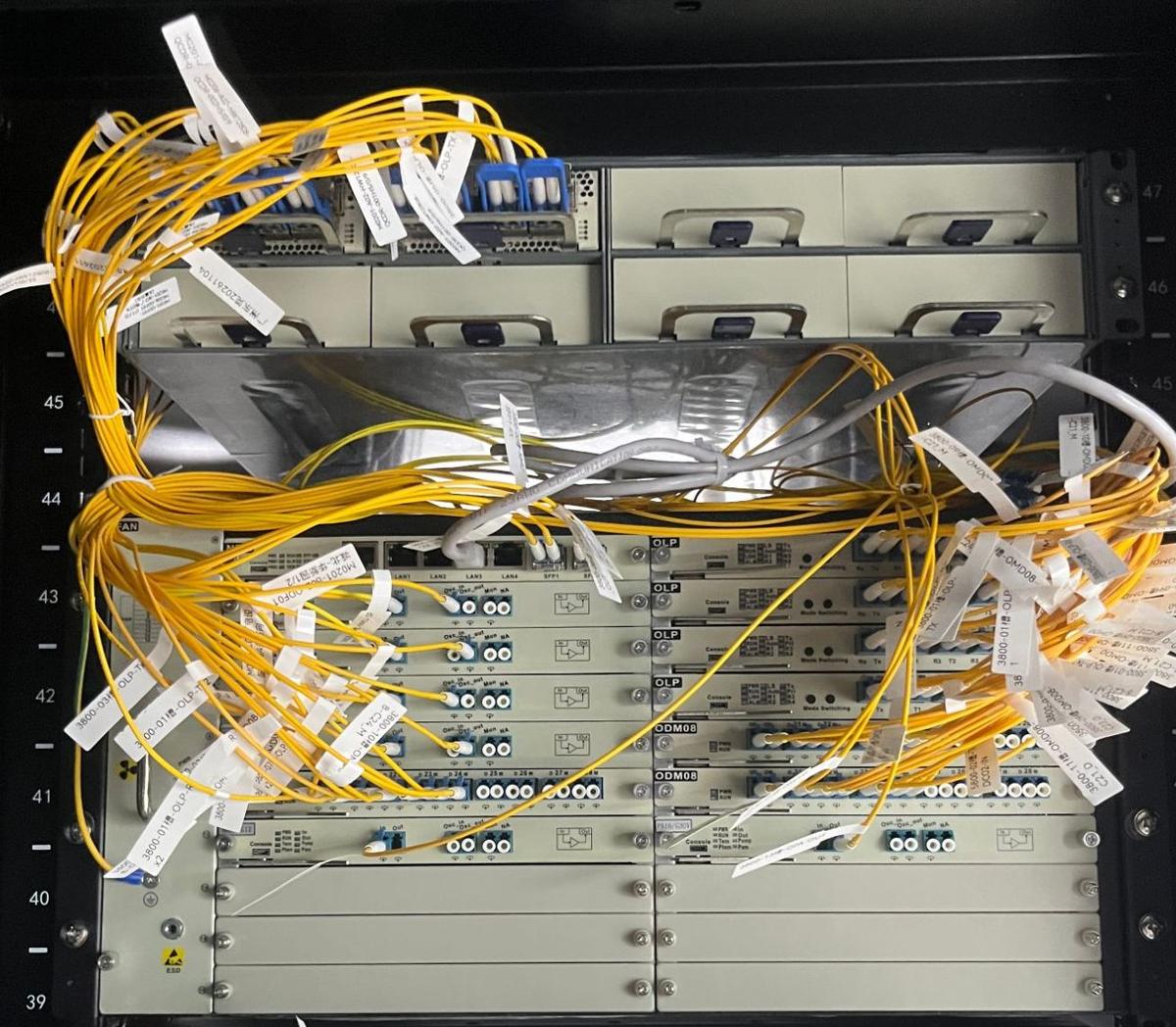
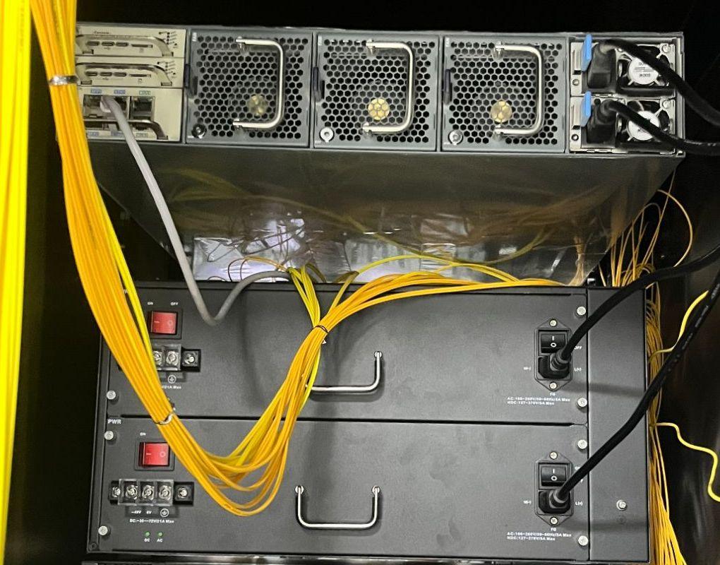
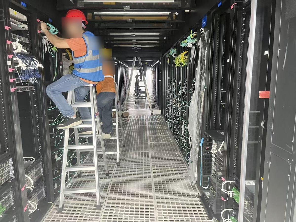
DWDM rack in a data center: OSP3800 chassis with OLP line protection, optical amplifier and 8-channel mux/demux cards, under a DCI5800 chassis.Rear of the same rack: DCI5800 fans and redundant power supplies above the DWDM chassis power modules.Installation and fiber patching during a data center deployment.
Reference architectures
DWDM with OLP line protection
16 × 100G wavelengths (C21–C37) on 40-channel MUX/DEMUX. An OLP 1+1 card at each end sends the signal on a primary and a secondary fiber route and switches to the healthy one when a route fails.
Six-site DWDM ring
Six sites on a ring with spans from 12 km / 4 dB to 61 km / 18 dB and up to 55 km / 20 dB. Booster, line and pre-amplifiers and dispersion compensation modules are placed per span.
Electrical MSP 1+1 with optical OLP protection
Five sites with 100G switches. At each site 4 × 100G client ports feed dual-line 400G transponder cards (T4Q2); each 400G line goes through an OLP card and 8-channel MUX/DEMUX, so a fiber cut or a card fault is covered. Spans from 10 km / 3 dB to 68.2 km / 18.66 dB; the main site carries 8 × 100G.
Large-granularity 100GE transport
Four 100GE switch ports are mapped onto one 400G wavelength (C21), and another four onto two 200G wavelengths (C22, C23), over one fiber pair.
Aggregating 10G and 100G onto 200G
Three 200G wavelengths on one fiber pair: 20 × 10G on the first, 2 × 100G on the second and 10 × 10G plus 1 × 100G on the third. Older 10G switches and new 100G switches share the same line.
250 km single span
Up to 40 wavelengths (C21–C60) over a single 250 km span with about 60 dB loss: booster EDFA and forward Raman at the transmitter (+8 dBm launch), backward Raman, pre-amplifier, dispersion compensation and booster at the receiver, with FEC on the transponders.